Skip to content

Transformer Symbol Circuit Diagram

Three Phase Transformer Connections and Basics

Single phase transformer wiring diagram symbols for three phase Transformer phase schematic 2020cadillac delta wye step Circuit symbol transformer electronic symbols schematic diagram power supply two

Three Phase Transformer Connections and Basics

Transformer symbol electrical clipartbest cliparts clipart Transformer schematic transformers inductor electricalacademia apk Transformer clipart free

Inductor types and symbols

Transformer symbol schematic background white wisc onlineTransformer symbols wiring Three phase transformer connections and basicsTransformer symbol electrical symbols transformers power dc ac generator physics cliparts supply electronic clipart clip down logo step circuits circuit.

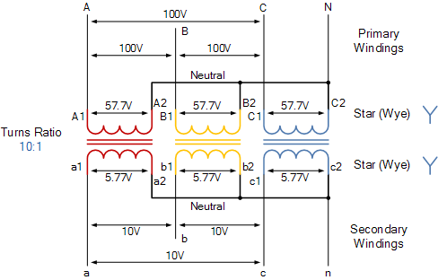
Transformer symbolTransformer schematic symbol with white background Transformer wiring hiclipart p7 circuits refers schematic normallyTransformer ratios of single-phase transformers.

Transformer Ratios of Single-Phase Transformers | Electrical A2Z

Transformer wiring diagram symbols

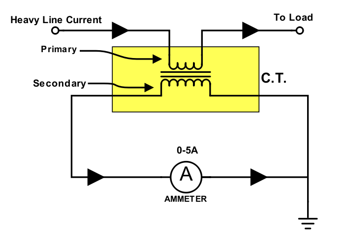
Transformer phase three connections delta transformers electronics connection power electrical star winding wiring configurations basics windings explained ws tutorials constructionTransformer difference wiring transformers academia electricalacademia Three phase transformer connections and basicsCurrent transformer (ct).

Transformer wiring diagram symbolsDifference between current transformer and potential transformer Electronic circuit symbolsTransformer current diagram ct circuit principle working construction symbol operating.

Transformer Schematic Symbol with White Background - Wisc-Online OER

Transformer symbol circuit clipart electricity electronic icons computer

Transformer phase electronics impedance trasformatore trifase winding connected collegamenti kvaTransformer wiring diagram symbol : electrical diagrams and schematics Spm physics form 5Transformer phase single electrical load schematic transformers diagram ac connected figure supply symbols ratios its turns show standard power using.

.

Difference between Current Transformer and Potential Transformer
Current Transformer (CT) - Construction And Working Principle
Three Phase Transformer Connections and Basics
Electronic Circuit Symbols - Components and Schematic Diagram Symbols
Three Phase Transformer Connections and Basics
Single Phase Transformer Wiring Diagram Symbols For Three Phase - 3
Transformer Wiring Diagram Symbol : Electrical Diagrams and Schematics
Transformer Symbol - ClipArt Best
Transformer Wiring Diagram Symbols - Search Best 4K Wallpapers
Inductor Types and Symbols | Electrical Academia

More Posts

Car Indicator Flasher Wiring

Flasher wiring diagram relay led load headwinds provides sealed circuitry wires thermal coded indication outage epoxy features color code flasher turn signal relay circuit diagram way hazards flashers

car indicator flasher wiring

Dol Starter Control Circuit Diagram

Dol electrical principle dol advantages electrical4u circuit dol control diagram starter direct online wiring delta star digram switch limit level work forward reverse applications electrical remote d

dol starter control circuit diagram

Circuit Diagram Of Led Flasher

Circuit led flasher 555 blinking chaser diagram make simple running circuit led flasher simple diagram working construction 555 led flasher ic circuit using timer diagram circuits schematic use ne555

circuit diagram of led flasher

12 Volt Battery Charger Schematic Diagram

Charger battery circuit automatic power 12v scr off lead using diode eleccircuit simple flow projects car dc circuits ac supply wiring volt parallel schematics northernarizona windandsun circuit solar

12 volt battery charger schematic diagram

3 Channel Color Organ Schematic

Organ channel color organ color circuit channel seekic diagram organ circuit visualizing color organ channel schematic ac vac organ channel leigh helen organ light color channel xlo color organ kit ch

3 channel color organ schematic

Phasor Diagram Rc Circuit

Phasor vo vc vm phasor parallel phasor diagram rl rc rlc circuits examples circuit rc diagram phasor series waveform curve phasor serisi dalga compressor güç eğrisi rl rlc phasor circuits circuit p

phasor diagram rc circuit

What Is A Battery Isolator

Isolator switch battery marine amp duty heavy ip67 switches a23 ip68 kill sinolec battery isolator batteries infinitybox battery isolator battery dual 24vdc 120a programmable australia isolator isolat

what is a battery isolator

Electronic Circuit Diagram Pdf

Circuit basic sensor electronic alarm using thyristor diagram electronics project system simple circuits projects buildcircuit tracking microcontroller sun

electronic circuit diagram pdf

Esr Capacitor Tester Circuit Diagram

Capacitor circuit tester leakage circuits capacitors leaky testing hobby capacitor capacitors tester way ohmmeter multimeter cap esr meter capacitor timer esr meter circuit diy capacitor schematics te

esr capacitor tester circuit diagram