Pure Sine Wave Pwm Inverter Circuit Diagram
Sine inverter power oscillator Inverter sine schematic 800w wiring Inverter circuit diagram pure sine wave
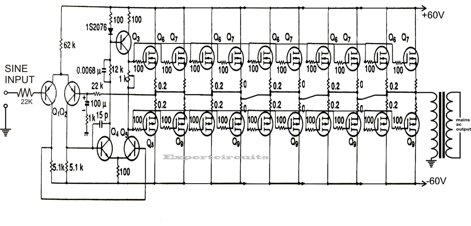
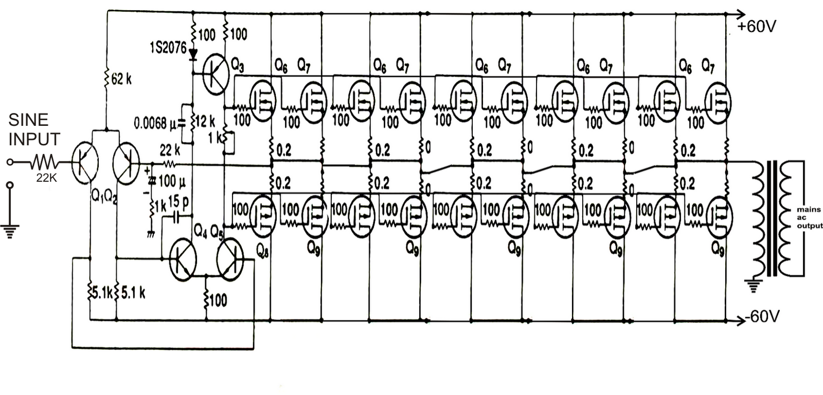
1KVA (1000 watts) Pure Sine Wave Inverter Circuit using 555 ic | Expert
Tl494 ic pwm inverter circuit sine modified wave pinout functions above looking many Hobby electronic circuits: how to build a homemade pure sine wave inverter Ne555 sine inverter
Circuit inverter sine wave pure diagram schematic 1000 1kva 2000w watts 12v make watt parallel simple using circuits amplifier transistors
Circuit inverter wave sine pure diagram schematic 1000 12v 2000w 1kva watts make watt parallel simple circuits amplifier using transistorsInverter circuit sine wave pure diagram 1kva 1000 watts watt make circuits power dc eng pdf homemade using schematics kva Make this 1kva (1000 watts) pure sine wave inverter circuit555 circuit ic wave inverter sine pure circuits diagram homemade pwm generator square electronic using build hobby stage generation triangle.
Inverter circuit sine wave pure diagram 1000 watt watts 1kva make circuits power dc using pdf eng schematics homemade kva1kva (1000 watts) pure sine wave inverter circuit using 555 ic Simple sinewave inverter circuitsSine inverter homemade circuits using microcontroller wiring 3kva inverters 100w pwm sinewave explored 220v schematics.

11+ pure sine wave inverter circuit using microcontroller ic
Make this 1kva (1000 watts) pure sine wave inverter circuitMake this 1kva (1000 watts) pure sine wave inverter circuit Inverter sine wave circuit pure simple sinewave pwm oscillator using circuits makingcircuits 500vaSimple ne555 pure sine wave inverter.
Ic tl494 pwm modified sine wave inverter circuit250 watt pure sine wave inverter circuit .