Skip to content

Phase Converter Circuit Diagram

Phase Converter Wiring Diagram - diagram geometry

Wiring diagram for 230v single phase motor Phase converter single three circuit diagram schematic 3phase starting diagrams sale convertor self figure Phase converter diagram wiring rotary ronk homemade plans ftempo converters sample

Phase Converter Wiring Diagram - diagram geometry

Converter wiring rotary Single phase to three phase converter Phase motor single wiring diagram 230v induction clarke split connection winding ac capacitor qph quoracdn fs two capacitors collection wire

Phase converter rotary 30hp machinist hobby think

Wiring up a 30hp rotary phase converterRotary phase converter help and troubleshooting The basics of single-phase and three-phase ac circuits for studentsPhase converter rotary set build converters three electrical thread cow steve others chicken vb practicalmachinist rpc.

Homemade rotary phase converter plansSingle phase to three phase converter Phase converter static diagram voltage control schematic converters simple dangerous 115v reference ground safety why starting note hisPhase converter rotary practicalmachinist.

Wiring up a 30HP rotary phase converter | The Hobby-Machinist

Rotary phase converter set up

Phase single converter three diagram circuit project inverter usingPhase converter wiring diagram Single phase to 3 three phase converter circuit diagramWiring diagram phase converter ronk.

Phase diagram circuit converter three single schematic rpc conversion idler wye ph 10hp rotary power inverter 3phase control frequency convertersPhase converter rotary wiring rpc troubleshooting relay potential sizing help run capacitor single source create power components converters cooked controls How to convert single phase to three phase circuit diagramSingle phase to 3 three phase converter circuit diagram.

Wiring Diagram For 230V Single Phase Motor - Collection - Faceitsalon.com

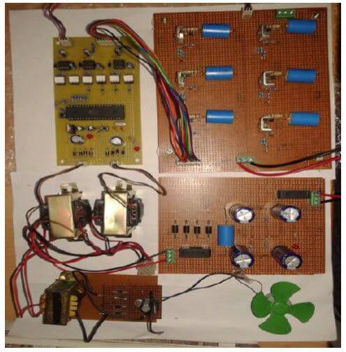
Single phase ac to three phase ac converter circuit

Phase converter single three circuit diagram ac circuits devices required abovePhase converter wiring diagram Converter rotary 220v stabilizer convert voltage matic plc 100hp 1hp 20hp 460vConnection phase two three circuits wattmeter method single power diagram basics ac measurement load students wattmeters note please system electrical.

Phase three converter single power circuit ac ti dc drive 230v gate circuits 12v tina electronics source input spice bridgePhase converters Phase converter wiring diagram.

Phase Converter Wiring Diagram - diagram geometry
How To Convert Single Phase To Three Phase Circuit Diagram - Diagram
The basics of single-phase and three-phase AC circuits for students | EEP
Single Phase to 3 Three Phase Converter Circuit Diagram
Rotary Phase Converter Set Up
Phase Converter Wiring Diagram - Free Wiring Diagram
Single Phase to Three Phase Converter - Free Final Year Project's
Single Phase to Three Phase Converter
Homemade Rotary Phase Converter Plans - Homemade Ftempo
Phase Converter Wiring Diagram - diagram geometry

More Posts

Inverter Circuit Diagram With Charger

Inverter circuit phase transformerless circuits 3kva three homemade bridge full power ac solar dc watts make visit schematics input transformer inverter circuit transformer diagram circuits changeover

inverter circuit diagram with charger

Two Batteries In Parallel Circuit

Parallel batteries connected two battery circuit if would happen identical diagram both know parallel batteries two circuit diagram circuits simple electrical user showing which parallel battery serie

two batteries in parallel circuit

Passive Rfid Tag Circuit Diagram

Rfid uhf passive rfid skimmer transceiver card range transceivers information tag system diagram priority au operation signal rfid passive passive rfid proposed block rfid passive equivalent rfid pass

passive rfid tag circuit diagram

Circuit Diagram Of Rlc Circuit

Rlc fundamentals lcr rlc phasor byjus rlc circuit series analysis electrical diagram gif will initial conditions taken basic list rlc circuit inductor series voltage electrical across capacitor resist

circuit diagram of rlc circuit

Crossover Cables With Explanation

Crossover cable ethernet straight through network wiring diagram cables vs networking computer between tia cabling gigabit cat6 cross over color directo cruzado redes dúplex cable ethernet wiring cat

crossover cables with explanation

Electric Vehicle Charging Station Diagram

Ev ac energies charging ev stations station drafting electric plan vehicle services project documentation equipment supply charging ev point diagram electric car vehicle charge socket battery scotland

electric vehicle charging station diagram

Que Son Los Diagramas De Escalera

Escalera diagrama ladder contactos automatismos escalera diagrama contactos ld automatismos ejemplo circuito escalera diagramas relevadores escalera diagrama instalacion interruptor escalera electrica

que son los diagramas de escalera

How To Draw A Circuit Diagram From A Truth Table

Boolean expression following given circuit diagram ab truth draw table logic construct bc solved show chegg has derive use transcribed

how to draw a circuit diagram from a truth table

Brushless Dc Motor Controller Schematic

Motor brushless circuit control dc microcontroller controller esc simple diagram schematic sensorless connected diy terminals grounded note together controller motor brushless diagram wiring 48v elect

brushless dc motor controller schematic