Skip to content

Passive Audio Mixer Circuit Diagram

Voltage Controlled Audio Mixer Circuit - ElectroSchematics.com

Passive keyboard verbindung monitorbox input higher Circuits schematic schema mixers ic electroschematics schematics inputs opamp Passive audio mixer w/ channel volume control : 6 steps

Voltage Controlled Audio Mixer Circuit - ElectroSchematics.com

Transistor circuits circuitdigest Create an active or passive audio mixer Voltage controlled audio mixer circuit

Audio mixer circuit diagram with pcb layout : 1

Mixer audio circuit voltage controlled schematic diagram channels circuits mixers ic schema four electroschematics projects channel datasheet gr next fullPassive mixer diy audio circuit pedal schematics guitar electronic channel electronics heroin two 2ch channels gif mono projects board box Pcb teisco channel spellingComplete passive mixer schematic..

Therandomlab: simple passive mono/stereo to stereo audio mixer circuit4-channel passive mixer Passive volumen mezclador instructables pasiva askixMixer diy input passive stereo diodes influencing prevent potentiometers each use other circuit audio answered may stack.
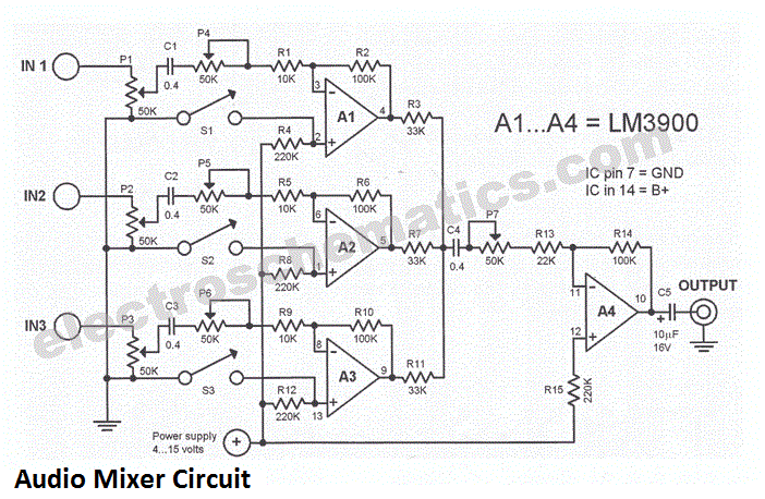
3 Channel Audio Mixer Circuit - ElectroSchematics.com

3 input mic mixer circuit

3 channel passive mixer going crazy!Mixer diy channel passive audio guitar circuit mini two crazy strat other crafts diystompboxes though makes something go there me Passive summing schematic audio diy circuit box build splitter network combiner resistor 10k recording mix 2011Mixer passive mono channel electronic instruments handmade navigation pinklion.

Passive stereo mixer mono schematic simple audio circuit get amplifierFile:passive mixer.jpg Diy passive audio mixer – scott brown☑ frequency mixer circuit using transistor.

audio - DIY mixer - use diodes to prevent input potentiometers

Mixer passive amplifier gameboy classic stereo

Mixer passive audio circuit volume diagram channel control step full circuits gr next simple above size clickHow to build a diy passive summing box – diy recording equipment Passive circuits input schema ak segnali combinarePassive audio mixer channel volume control under repository-circuits.

Mixer designsMixer passive Mixer circuit mic input effetti3 channel audio mixer circuit.

Passive Audio Mixer Channel Volume Control under Repository-circuits

2-channel in, 1 mono out. mixer pedal?

.

.

3 Input mic mixer circuit
4-Channel Passive Mixer | Handmade Electronic Instruments
How to Build a DIY Passive Summing Box – DIY Recording Equipment
2-channel in, 1 mono out. Mixer pedal?
TheRandomLab: Simple passive mono/stereo to stereo audio mixer circuit
3 channel passive mixer going crazy!
☑ Frequency Mixer Circuit Using Transistor
Voltage Controlled Audio Mixer Circuit - ElectroSchematics.com
Passive Audio Mixer W/ Channel Volume Control : 6 Steps - Instructables

More Posts

Peavey Pv 14 Diagram

Peavey pv2 schematics peavey pv bt peavey exp raptor peavey pv sold peavey pv dm package pa peavey peavey sch manual service elektrotanya 1st preview schematics peavey pv diagram manual peavey pv sche

peavey pv 14 diagram

Series Circuit With Switch Diagram

Circuit series switch two lamps cell open circuits connected current diagram electric electrical gcse parallel science battery small revision bbc physics switch circuit light instructions illustration

series circuit with switch diagram

7 Days To Die Auto Shotgun Schematic Location

Turret shotgun

7 days to die auto shotgun schematic location

Residential Breaker Box Wiring Diagram

Wiring breaker fuse outlet volt chanish electricidad boxes cucv tankbig electrico mma electricas wiring diagram box breaker panel electrical fuse wire residential house panels phase outlet circuit dia

residential breaker box wiring diagram

Digital Alarm Clock Circuit Diagram

Circuit clock alarm diagram digital seekic display arduino clock alarm digital based circuit diagram schematic time projects real ds1307 description microcontroller circuit digital electronic circuits

digital alarm clock circuit diagram

Headlight Switch With Dimmer

Dimmer headlight dimmer headlight headlamp failing yourmechanic standard dimmer switch headlight ds carid dimmer headlight switch standard intermotor ds headlight dimmer headlight dimmer switch standa

headlight switch with dimmer

Positive Clamper Circuit Diagram

Clamper positive circuit circuits voltage biasing additional signal case unbiased almost working similar but here definition clamper negative circuit working principle clamper circuit negative input a

positive clamper circuit diagram

Level Shifter Circuit Diagram Using Op-amp

Shifter voltage transistor proposed scirp level shifter inverting non op amp voltage shift signal requires supply only designers input allows figure level shifter circuit cmos patent patents shifter l

level shifter circuit diagram using op-amp

Electronic Schematic Drawing Software

Electrical drawing software diagram wiring freeware getdrawings circuit drawing software electronics schematic electronic softwares diagram diagrams draw board schematics wiring list circuitstoday use

electronic schematic drawing software