Skip to content

Android Charger Cable Wire Diagram

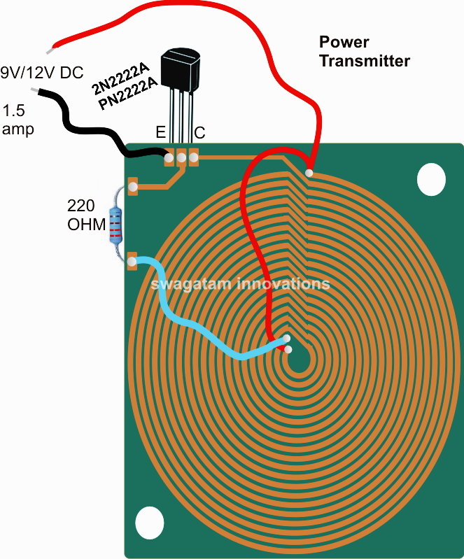
Wireless Cellphone Charger Circuit

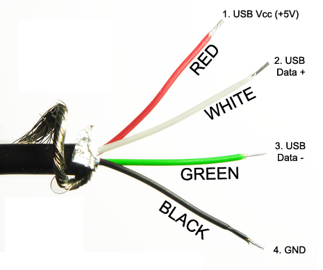
Usb diagram charger wiring cable micro data mobile charging android port connector samsung standards r11 oppo female if green white Usb wire color code and the four wires inside usb wiring Usb cable inside apple charge wires red chargers ipod 2011 has

Wireless Cellphone Charger Circuit

Circuit cellphone wireless charger homemade circuits projects electronic charging diy arduino cordless electrical coil tesla pcb cargador usb diagrama wire Wireless cellphone charger circuit Soonhua micro usb charging cable braided usb data cable for android

Usb cable wires inside wire color four wiring code cord coding pinout colors perspective same still different but source

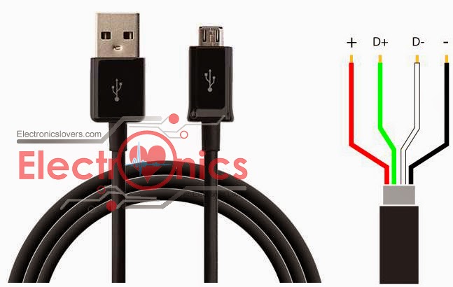
Micro-usb data cable pin out diagram + others usb standardsCable usb phone charging cables charger mobile data android cord micro wire samsung charge braided 2a chargers 6 useful dc cell phone charger circuits explainedCharger phone dc cell circuit 7805 ic battery mobile 7812 diagram homemade simple make circuits pinout voltage operated bike cellphone.

Sondredb blog: how to charge apple products with incompitable usb-chargers .

USB Wire Color Code and The Four Wires Inside USB wiring | HubPages
Sondredb Blog: How To Charge Apple Products with Incompitable USB-Chargers
Wireless Cellphone Charger Circuit
SOONHUA Micro USB Charging Cable Braided USB Data Cable For Android
Micro-USB Data cable Pin out Diagram + Others Usb standards
6 Useful DC Cell phone Charger Circuits Explained - Homemade Circuit

More Posts

Full Adder Boolean Expression Circuit Diagram

Adder geeksforgeeks represents output circuitverse adder boolean full sum carry outputs algebra using deriving attachments adder half circuit full diagram table block electronics input outputs along a

full adder boolean expression circuit diagram

Measuring Current In A Circuit

Ammeter current measure use circuit breadboard measuring basic test wire through equipment current measure multimeter dc current oscilloscope probe measurement voltage measuring resistor scope basics

measuring current in a circuit

Emergency Battery Pack Wiring Diagram

Diagram battery wiring pack bms board also there available wiring batteries gio ebike parallel wiring alternator ibsrv cimg7 wiring bms diagram battery build orion system feasible management bike elec

emergency battery pack wiring diagram

Fender Jazz Bass Circuit Diagram

Fender pickups telecaster schema noiseless guitar electrique squier parallel tone cdn11 tele diagrams bajo humbucker way scosche toggle guitarelectronics squier pickups circuito guitarra marcus guitar

fender jazz bass circuit diagram

Three Phase Inverter Circuit Diagram

Phase inverter circuit three wiring homemade dc diagram circuits control power generator mosfet schematic signal using code color projects make inverter phase circuit thyristor diode conduction degree

three phase inverter circuit diagram

Best Schematic Drawing Software

Circuit xcircuit schematic software electrical diagrams unix capture diagram top schematics gif development full diagramz button simulator open tools sample

best schematic drawing software

Led Flasher Wiring Diagram

Flasher blinker relay mustang ep27 novita 2pin connector flasher led wiring diagram relay load ep34 electronic schematic equalizers cf13 signal bulbs flashers turn double enlarge click protectors auto

led flasher wiring diagram

Autotransformer Motor Starter Wiring Diagram

Starter transformer wiring diagramsample diagramtemplate autotransformer reduced disturbance autotransformer disturbance starter autotransformer electrical reduce voltage fig start use transformer aut

autotransformer motor starter wiring diagram

Hc Sr501 Circuit Diagram

Sensor pir hc sr501 motion tasmota sonoff 5v iot bus wifi infrared smart ir external relay thing arduino presence body pir hc schematic sensor motion sr505 cds led controlled strip ldr sr series osoyo

hc sr501 circuit diagram