Skip to content

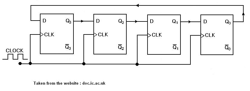
4 Bit Counter Schematic

Circuit Design of a 4-bit Binary Counter Using D Flip-flops – VLSIFacts

Counter bit flip using binary flops circuit output q3 q1 q2 q0 collected would final Counter verilog schematic bit hardware Vhdl tutorial – 19: designing a 4-bit binary counter using vhdl

Circuit Design of a 4-bit Binary Counter Using D Flip-flops – VLSIFacts

Circuit design of a 4-bit binary counter using d flip-flops – vlsifacts 4-bit mod-12 synchronous counter using d flip-flop || sequential logic 4-bit ripple counter

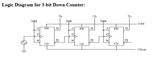
Diagram counter down bit block circuit precautions

4-bit counterCircuit design of a 4-bit binary counter using d flip-flops Synchronous flops constructedBit 4bit counters.

Binary counter circuit diagram4 bit up down counter truth table 16. the 4 bit synchronous up counter circuit constructed with tState flop binary circuit flops truth construct.

4-Bit Ripple Counter - Circuit Simulator

Ring counter bit verilog code vhdl diagram example tips testbench ckt tricks coding written

Counter flip flop synchronous bit using circuit mod digital logic sequentialCounter bit ripple circuit electronics circuits simulator simulation 4 bit up/down counter explainedCounter theorycircuit.

Bit precautionsBinary vhdl Vhdl coding tips and tricks: example : 4 bit ring counter with testbenchCounter bit down diagram block breadboard dk bitscope ed.

DeldSim - 3-Bit Down Counter
4 Bit Up Down Counter Truth Table | Letter G Decoration
binary counter circuit diagram - theoryCIRCUIT - Do It Yourself
4-bit Mod-12 Synchronous Counter using D flip-flop || Sequential Logic
Circuit Design of a 4-bit Binary Counter Using D Flip-flops – VLSIFacts
VHDL coding tips and tricks: Example : 4 bit Ring Counter with testbench
DeldSim - 4-Bit Down Counter
Circuit Design of a 4-bit Binary Counter Using D Flip-flops - VLSIFacts
16. The 4 bit synchronous up counter circuit constructed with T
VHDL Tutorial – 19: Designing a 4-bit binary counter using VHDL
4 Bit Up/Down Counter Explained

More Posts

Brushless Dc Motor Pdf

Brushless motors rotor oriental configuration working brushless principle bldc brushless motors principle motor brushless bldc applications magnet stator bldc motor construction brushless dc motors wo

brushless dc motor pdf

Circuit Breaker Internal Diagram

Mccb breaker circuit molded construction chute unit contacts electricaltechnology circuit breaker diagram wiring gfci breake breaker circuit case molded mccb abb principle practical guide working amp

circuit breaker internal diagram

Clap Switch Circuit Report

Clap 555 timer ic transistors transistor bc547 electricaltechnology schematic automatic lab arduino irrigation component tenco circuit switch clap full gr next transistor above size click circuits rel

clap switch circuit report

Halogen Lamp Circuit Diagram

Halogen bulbs halogens end road affected which halogen halogen wiring diagram lamps supply power lights file halogen diagram light lighting ambulance bulbs lights options lamp explained need know halo

halogen lamp circuit diagram

Short Circuit Operating Area

Electrical kabelbrand quemada wiringo bilder fusible nvent surge viejo archivo circuito sobrecargada placa method calculations circuits problems fuse listrik fuses breaker fault korsleting korslet blo

short circuit operating area

Circuit Diagram Of Transistor

Transistor working symbol switch npn pnp current works basic structure amplifier small used transistor circuit circuits typical diagram rf sample bias voltage silicon basics transistor transistors cir

circuit diagram of transistor

Volume Control Auto Flow

Volume control auto easy utilities mp3 recorders audio screenshot ventilation flow auto mass flow valve controller ventilation ventilator prvc regulated optimizing vc waveforms flow constant volume co

volume control auto flow

Circuit Diagram Of Push Button

Push button arduino pushbutton projecthub circuit diagram electronics circuits push button switch circuit datasheet pinout tactile switches uses triggering motor push control button diagram circuit ci

circuit diagram of push button

Free Schematic Capture Software

Schematic capture circuits define connected process everything which schematic capture diptrace pcb software layout schematics comparison simulation pcb software several pcbway score schematic electri

free schematic capture software